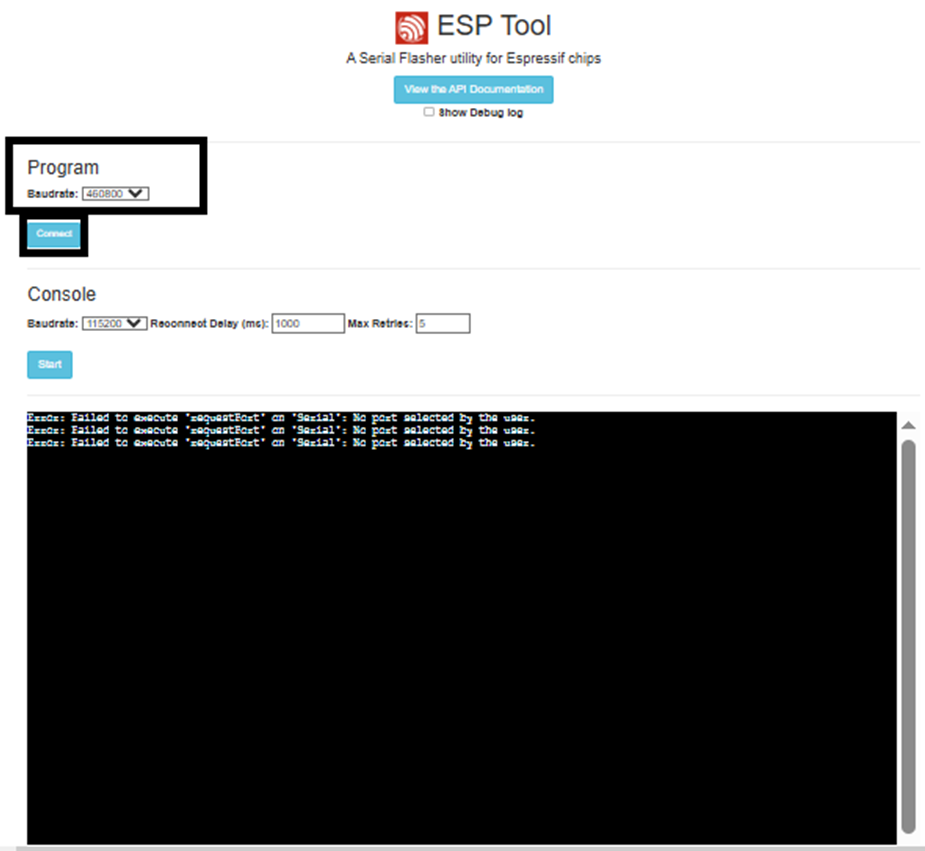
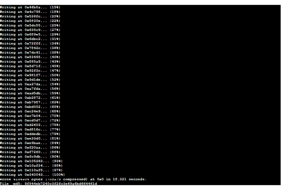
How It Works Use Cases Features Demo Integrations Resources Blog Contact
Book Demo
📋 Jump to Section
Integration Guide

Waveshare ESP32-S3
WiFi Relay with DoorVi

Step-by-step guide to configure the Waveshare ESP32-S3 WiFi Relay Module with the DoorVi control panel — from firmware flashing to adding a lock.

🔧 7 Steps 📡 MQTT Setup ⚡ ESP32-S3 🔒 Relay Lock
🔌

Prerequisites — Hardware Setup

Before you begin, make sure the relay is connected to your computer

Make sure that you have connected the Waveshare ESP32-S3 WiFi Relay Module to your computer using a Type-C cable or any other compatible cable.
Waveshare ESP32-S3 relay module connected via Type-C cable
Waveshare ESP32-S3 relay module connected to a laptop via Type-C cable
Save image as images/waveshare-hardware.png
⚠️ Ensure the relay is powered and the USB cable supports data transfer (not just charging) before proceeding.

Step 1 — Add Relay Device in DoorVi

Register your relay in the DoorVi Multi Control Panel

1
Log in to the DoorVi Multi Control Panel at https://multi.doorvi.co/ using the credentials assigned to you.
2
Go to the left-hand side menu and select "Relay Manager."
3
Click on "Add Relay." A form will appear.
4
In the first two fields (Relay Type and Device Type), choose "DoorVi."
5
In the "Device Name" field, enter any name you prefer (e.g., Main Gate, Back Door, Gate 1).
6
In the MQTT Server field, choose the server closest to your country. (Dedicated servers in your region can be set up if needed.)
7
In the "Number of Channels" field, select "6" — this relay has 6 channels.
8
Click the "Confirm" button to save the relay device.
DoorVi Relay Manager — Add Relay form filled in
DoorVi MulTi Relay Manager showing Add Relay form with DoorVi type, device name, MQTT server and 6 channels
Save image as images/waveshare-step1-add-relay.png
🔑

Step 1b — Get MQTT Credentials

Copy MQTT details — you'll need them later during configuration

1
On the next screen, you will see the device name you just created in the Relay Manager list.
2
Click on the yellow icon next to your device to open the Subscription Addresses panel.
3
Keep this screen open. You will need the following values later during configuration:
MQTT Publish Topic
Copy from the yellow icon panel
MQTT Subscribe Topic
Copy from the yellow icon panel
MQTT Username
Copy from the yellow icon panel
MQTT Password
Copy from the yellow icon panel
Relay Manager — Subscription Addresses panel (yellow icon)
DoorVi Relay Manager showing Subscription Addresses popup with MQTT Pub Topic, Sub Topic, Username and Password
Save image as images/waveshare-step1b-mqtt.png
💡 You will copy and paste these values into the corresponding fields in Step 6 when we continue the setup. Keep this tab open.
⬇️

Step 2 — Download the Firmware (.bin)

Download the ESP32-S3 setup file to your computer

1
Download the firmware setup file (.bin) using the link below. Simply click the link and the file will automatically download to your computer.
ℹ️ Save this file in a location you can easily find — you will need to upload it in Step 4.
🌐

Step 3 — Open the ESP Flashing Tool

Connect your device via the browser-based ESP Tool

1
Open the following URL in your browser: https://espressif.github.io/esptool-js/
2
Click on the Baud Rate dropdown menu and select 460800 from the list.
3
Click on "Connect." A pop-up window will appear asking you to select the communication port.
4
Choose the COM port (or serial port) where your USB device is connected and click Connect.
ESP Tool — baud rate set to 460800, Connect button
ESP Tool web page showing Baudrate set to 460800 and Connect button
Save image as images/waveshare-step3-esptool.png
How to find your COM port / Serial port:
🪟 Windows — Finding the COM Port
1
Press Windows Key + X and select Device Manager (or search for it from the Start menu).
2
Expand the Ports (COM & LPT) section.
3
Look for entries such as: USB Serial Device (COM3), CH340 (COM5)
4
Note the COM number in brackets and select that same port in the Connect pop-up.
💡 If unsure, unplug the USB cable and plug it back in — the COM port that appears/disappears is your device.
🍎 Mac — Finding the Serial Port
1
Connect the device via USB.
2
Open Terminal (Applications → Utilities → Terminal).
3
Type the following command and press Enter:
ls /dev/tty.*
Look for entries like /dev/tty.usbserial-xxxx or /dev/tty.SLAB_USBtoUART
💡 Run the command before and after plugging in the device — the newly appearing entry is your device.

Step 4 — Flash the Firmware

Erase flash memory and program the ESP32-S3 with the DoorVi firmware

1
After connecting, you will see the flashing screen. Click on the "Erase Flash" button.
2
In the "Flash Address" field, replace the default value 0x1000 with 0x0.
3
Click on "Choose File" and upload the .bin file downloaded in Step 2.
4
Click on the "Program" button to begin flashing the firmware.
5
A console/terminal window will display the flashing progress. Wait until the process reaches 100% completion before disconnecting the device.
ESP Tool — Flash Address set to 0x0, .bin file chosen, Program button
ESP Tool showing Erase Flash button, Flash Address 0x0, Choose File with esp32s3.bin and Program button
Save image as images/waveshare-step4-program.png
ESP Tool console showing flashing progress reaching 100%
ESP Tool console showing Writing progress from 15% to 100% completion
Save image as images/waveshare-step4-progress.png
⚠️ Do not disconnect the device until the progress reaches 100%. Disconnecting early may corrupt the firmware.
📶

Step 5 — Connect to DoorVi Setup WiFi

Reconnect the device and join the DoorVi-setup WiFi network

1
Disconnect the USB cable from the device.
2
Wait a few seconds, then reconnect the USB cable.
3
After the device powers up again, you should see a new Wi-Fi network named DoorVi-setup0000 in your computer's available Wi-Fi list.
4
Connect to this network using the password below.
📶
WiFi Network Name
DoorVi-setup0000
Password
doorvi123
⚙️

Step 6 — Configure WiFi & MQTT

Enter your WiFi and MQTT credentials in the DoorVi Setup page

1
Once connected to DoorVi-setup0000, open your browser and go to: 192.168.4.1
2
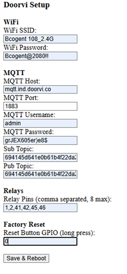
The Doorvi Setup configuration page will load. Fill in all the sections below carefully.
1. WiFi Details
i
In the WiFi SSID field, enter the WiFi network name you want the relay to connect to.
ii
In the WiFi Password field, enter your WiFi password.
⚠️ Select your 2.4 GHz WiFi network — the relay only works on 2.4 GHz, not 5 GHz.
2. MQTT Settings
i
In the MQTT Host field, enter based on your region:
For India
mqtt.ind.doorvi.co
Outside India
mqtt.us.doorvi.co
⚠️ Do not include mqtt:// or https:// prefix.
MQTT Port
1883
MQTT Username
admin
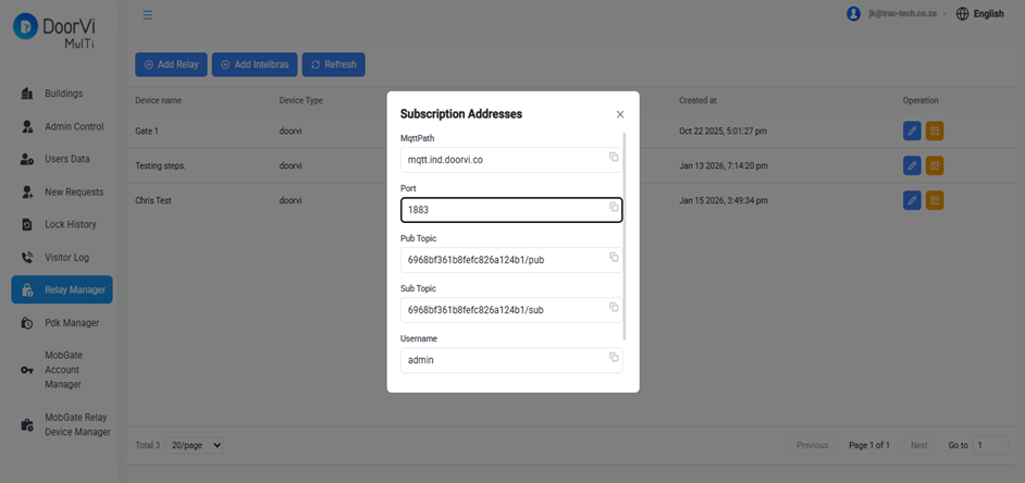
3. MQTT Credentials Important

Copy from the DoorVi Control Panel (screen left open in Step 1b):

i
Paste the MQTT Publish Topic into the Pub Topic field.
ii
Paste the MQTT Subscribe Topic into the Sub Topic field.
iii
Paste the MQTT Username and MQTT Password into their respective fields.
4. Relay Pins, Factory Reset & Behaviour
i
Relay Pins — Keep the values as shown. They may vary per device; we will help you verify.
ii
Factory Reset (Reset Button GPIO) — Enter 0.
iii
Behaviour when internet is lost — 1 = lock stays open, 0 = lock stays locked.
iv
Click "Save & Reboot." The device will restart and reconnect to your WiFi automatically.
After Save & Reboot, your computer disconnects from DoorVi-setup-0000 and your normal WiFi reconnects within seconds.
Doorvi Setup — 192.168.4.1
Doorvi Setup configuration page showing WiFi SSID, WiFi Password, MQTT Host, Port, Username, Password, Sub Topic, Pub Topic, Relay Pins and Save & Reboot button
Save image as images/waveshare-step6-config.png
🔒

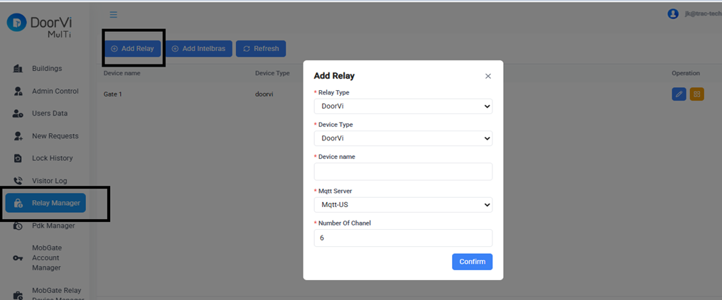
Step 7 — Add Relay Lock in DoorVi

Link the relay to a building and configure the lock

1
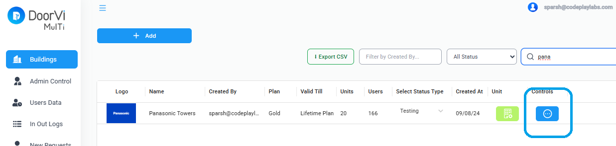
Go back to the DoorVi Multi Control Panel home page.
2
Select the "Control" section (the circular control icon) of the building where you want to configure the relay.
3
Choose the "Locks" option.
4
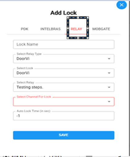
Click on "Add Lock" and then select the third option — "Relay."
DoorVi Buildings — Control icon per building
DoorVi MulTi Buildings list showing Control icon button for each building
Save image as images/waveshare-step7-buildings.png
Fill in the Add Lock form:
i
In the Lock Name field, enter a name based on where the lock will be used — e.g., Main Entrance, Gate No. 1, Exit Gate.
ii
Choose "DoorVi" in both the second (Select Lock) and third (Select Lock Type) fields.
iii
Select the Relay that you named in Step 1 from the dropdown.
iv
Choose the channel you want to use from the available 6 channels.
v
Set the Auto Lock Time (in sec):
-1
Lock remains open until manually locked
5
Returns to closed after 5 seconds
vi
Click "Save" to complete the setup.
Add Lock form — Relay tab
DoorVi Add Lock dialog showing Relay tab selected with Lock Name, Select Lock, Select Relay and Channel fields
Save image as images/waveshare-step7-add-lock.png

Verify & Done

Check relay status and confirm the setup is complete

1
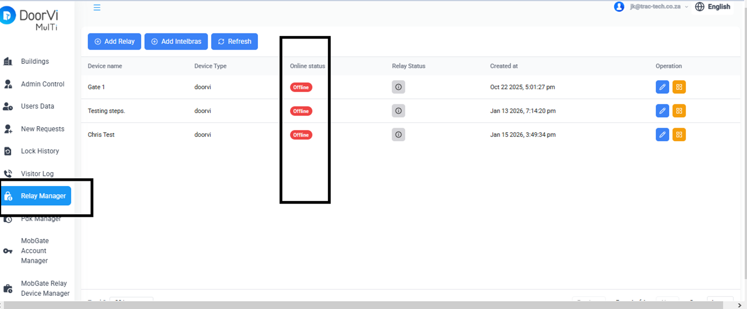
Click on "Relay Manager" from the left-hand menu on the DoorVi Control Panel home page.
2
You will be able to see whether the relay is online or offline.
3
Once online, residents will see the "Manage Locks" option on their DoorVi app home page and can operate the relay from their smartphone.
Relay Manager — showing relay online/offline status
DoorVi MulTi Relay Manager showing device list with Online Status, Relay Status and Operation columns
Save image as images/waveshare-verify-relay.png
🎉

Setup complete!

Your Waveshare ESP32-S3 relay is now linked to DoorVi. Residents can answer visitor calls and operate the relay lock directly from the DoorVi app on their smartphone.
💬 Need assistance? Contact our support team at jatin@doorvi.co or media@doorvi.co.